Networks
Topologies
A network topology is the arrangement of the devices and the connections between them in a network. It describes the pattern the network follows — which device links to which, and how the cables or wireless links are laid out — rather than the make of the hardware or how large the network is.
Network designers choose a topology before anything is built, because the arrangement affects how much cabling is needed, how data travels to the right device, and what happens when a link stops working. Two networks can contain exactly the same computers and printers yet behave very differently if their topologies differ.
The three topologies
| Topology | How the devices and connections are arranged |
|---|---|
| Bus | Every device taps into one shared main cable running through the network, with each end of that cable closed off so signals stop there. |
| Star | Each device has its own connection to a single central device, which sits in the middle and passes data on. |
| Mesh | Devices connect to several other devices rather than to one centre, so data can take more than one route. |
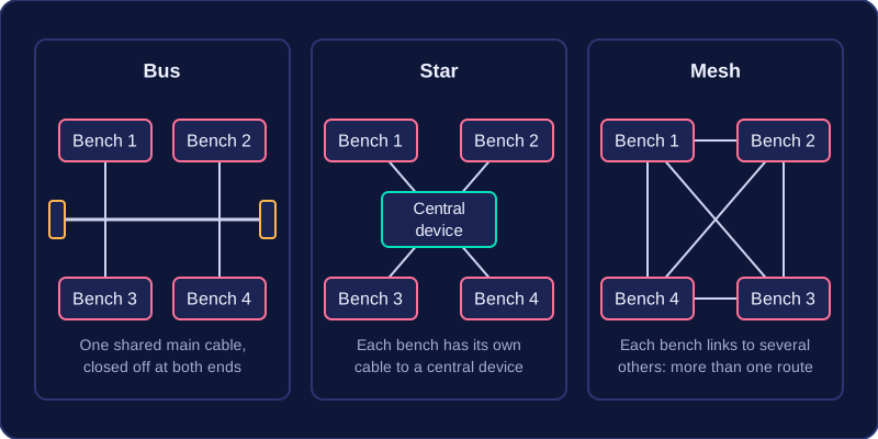
Look at the difference in shape. Bus and star both rely on one item at the heart of the arrangement — a main cable in one case, a central device in the other — while a mesh spreads its connections around, so the network does not hang on any single device or link. For example, a small bike repair workshop could run one shared cable past the workbenches, give each bench its own cable to a central box, or connect each bench to several of the others; the benches are identical, but each arrangement is a different topology.
In a star topology, every device has its own cable to a central switch or hub. When one device sends data, it travels to the central device first; a switch then forwards it to the destination device. The central device is a switch or hub, and a router that contains a switch can also act as the centre, but a server is not the central device.
Fast, separate connections
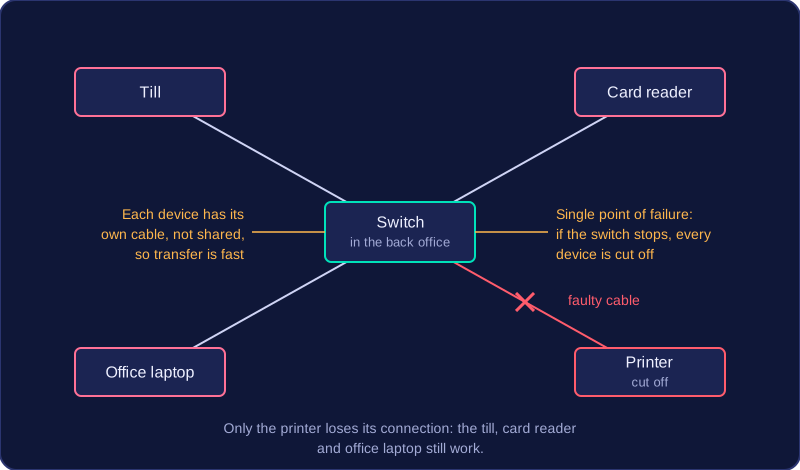
Each cable is used only by the device at its end, so it is not shared with other devices. This gives fast data transfer. If one cable is damaged or one device breaks, only that device loses its connection; the rest keep working. For example, imagine you run a small café and connect its till, card reader, office laptop and printer by cable to a switch in the back office. If the printer cable is faulty, the till, card reader and office laptop still work.
Extra hardware and a single point of failure
A star needs extra hardware: the central switch or hub and a separate cable for every device. Laying all those cables can make setup difficult and expensive, especially if devices are spread across a building. The number of devices is limited by the number of connections, or ports, on the central switch or hub. Most importantly, the central switch or hub is a single point of failure: if it stops working, every device loses its network connection.
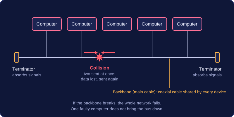
A bus topology connects every device to one shared backbone, also called the main cable. This backbone is coaxial cable, and each device connects to it rather than having its own cable to a central device.
At both ends of the backbone there is a terminator. It absorbs signals so they do not reflect back along the cable. If a terminator is missing or faulty, reflected signals interfere with new transmissions and the network does not work properly.
Why a bus can be useful
A bus needs less cable than topologies that run a separate cable to every device, so installation can be cheaper. Adding a device is also easy: it only has to connect to the main cable, with no new link back to a central device.
Drawbacks of sharing one cable
Because every device uses the same backbone, only one device can transmit at a time. If two devices transmit together, their signals collide, so data is lost and must be sent again. As more devices or users are added, collisions become more frequent and throughput falls.
For example, if eight computers in a youth club office share one backbone and several send print jobs at once, the collisions make files take longer to arrive. The shared cable is also a security risk: every device on the bus can see every data packet, even packets meant for another device.
If the main cable breaks, the whole network fails because no device can reach the others. A single faulty device does not bring the bus down; it is failure of the backbone or terminators that does.
In a mesh topology each node connects to more than one other node, and every node acts as a router: it takes in data, works out where the data needs to go and passes it on. With so many links there is usually more than one possible path between two devices.
Why a mesh is resilient
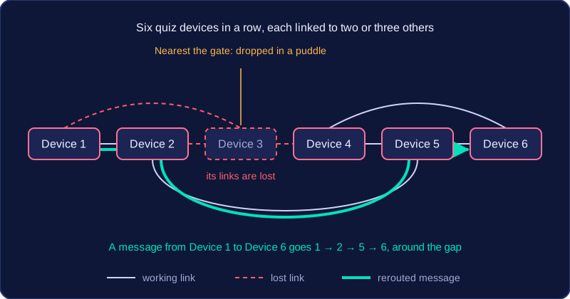
The spare links are called redundancy. They give data alternative routes, so if a cable is cut or a device is switched off, traffic simply travels a different way. This means a mesh has no single point of failure and keeps working when part of it breaks, which is why it is described as resilient.
A mesh also lets different devices transmit at the same time, and each node can send and receive together, so lots of traffic can flow without everything queueing behind one shared cable. Nodes can be added, moved or removed without disrupting everyone else. This is easiest when the mesh is software-based: the nodes are programmed to discover each other and choose routes automatically, so a new node just needs power and a wireless connection. A wired mesh is harder to extend, because each new node needs physical cabling and a network interface card.
For example, imagine a row of six handheld quiz devices at an outdoor activity centre. Each one talks to two or three of its neighbours and passes answers along, so when the device nearest the gate is dropped in a puddle, the remaining five route the messages around the gap and the quiz carries on.
What a mesh costs you
All that redundancy has a price. Extra connections add cost and complexity, and a wired mesh is expensive to install because every link is a cable that has to be bought and laid. With so many devices and paths, maintenance and administration are difficult: tracking down a faulty link or updating settings across a busy mesh takes far more effort than looking after one central switch.
Full mesh and partial mesh are two ways of arranging the links between nodes. A node is any device that sends or receives data, such as a computer, switch or sensor.
Full mesh
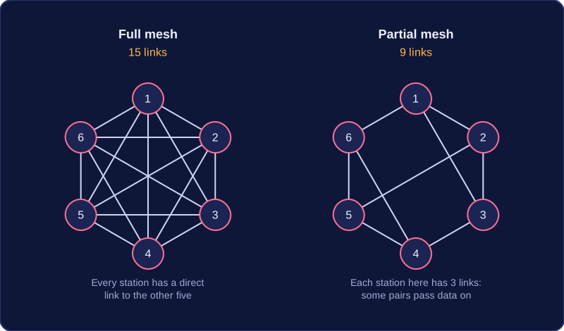
In a full mesh, every node is connected directly to every other node. Data can travel straight to its destination without passing through another device, because every pair of nodes has its own link. If one link fails, traffic can take a different route, so a full mesh gives maximum redundancy.
The cost is the number of connections. Each extra node needs a direct link to every node already there:
| Nodes | Direct links in a full mesh |
|---|---|
| 4 | 6 |
| 6 | 15 |
| 8 | 28 |
For example, six weather stations on a mountain range could share readings in a full mesh, but that means installing and maintaining 15 links. Each station would need five separate cables, one running to each of the other five stations, so even a small network ends up needing a lot of hardware.
Partial mesh
A partial mesh connects some nodes to several other nodes, but not every node to every other node. The same six weather stations could each link to two or three neighbours, using about nine links instead of 15. Some pairs cannot talk directly, so their data is passed through a station in between. Even so, most pairs still have more than one route, so a broken link rarely cuts anything off.
Choosing between them
Partial mesh is the version used most of the time. It keeps the alternative routes of a mesh while cutting the number of connections, which reduces cost. Larger networks often combine several star topologies with a partial mesh linking their central switches, so the whole network gains extra routes. A full mesh is reserved for small networks, or for a few key nodes, where every direct route matters.
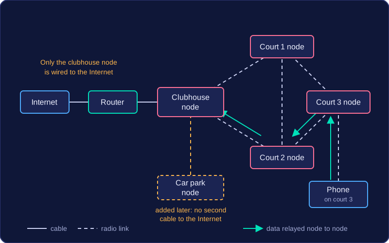
A wireless mesh is a set of nodes that pass data to each other using radio signals, so one network can cover a large area such as a holiday park spread over several fields. Each node is a wireless access point. A device joins the node with the strongest signal, usually the nearest, and the nodes relay data between themselves.
Only one node needs a wired connection to the Internet. That node connects to a router with a cable. Every other node reaches the Internet by passing data from node to node until it arrives at that wired node. This saves running a cable to every access point.
Why adding nodes helps
- More routes for data: with more nodes there are more paths across the mesh, so if one route is busy or not working, data can be sent another way and devices stay connected.
- More bandwidth: bandwidth is the maximum amount of data the network can carry in a given time. Each node handles the devices around it, and different nodes can send data at the same time, so the mesh as a whole can carry more traffic.
- Stronger signal strength: radio signals get weaker as they travel. Placing nodes closer to the devices, and closer to each other, gives a stronger signal, so devices disconnect less often and transfers are faster.
For example, a tennis club puts its wired node in the clubhouse and adds one node by each of its three courts. A phone used on the far court connects to that court's node, which relays the data from node to node back to the clubhouse. Adding a node in the car park later extends the Wi-Fi there without a second cable to the Internet.