Boolean Logic
Truth tables
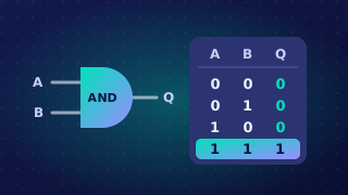
A truth table records all the input combinations a logic circuit can receive and the output it gives for each one. It lets you see the full behaviour of the circuit without building it.
The number of rows below the heading row is 2 raised to the power of the number of inputs: one input needs 2 rows, two inputs need 4 rows and three inputs need 8 rows. Each extra input doubles the count, because that input can be either 1 or 0, so every row you already had becomes two rows.
Counting in binary
A reliable way to fill the input columns is to treat them as binary numbers and count upwards. With two inputs the patterns run 00, 01, 10 then 11. With three inputs start at 000 and keep counting until you reach 111. This makes it easy to see that no combination is missed and none is repeated. The rows can be in any order and still be correct, as long as every combination appears once.
More than one gate
When a circuit has more than one gate, add a helper column for each gate that sits between the inputs and the final gate. Work out those columns first, then use them to find the final output. For example, for X = (A OR B) AND (B OR C), the helper columns are A OR B and B OR C:
| A | B | C | A OR B | B OR C | X |
|---|---|---|---|---|---|
| 0 | 0 | 0 | 0 | 0 | 0 |
| 0 | 0 | 1 | 0 | 1 | 0 |
| 0 | 1 | 0 | 1 | 1 | 1 |
| 0 | 1 | 1 | 1 | 1 | 1 |
| 1 | 0 | 0 | 1 | 0 | 0 |
| 1 | 0 | 1 | 1 | 1 | 1 |
| 1 | 1 | 0 | 1 | 1 | 1 |
| 1 | 1 | 1 | 1 | 1 | 1 |
The final column is found by applying AND to the two helper values in each row, so you never have to hold several steps in your head at once.
Practise this
OCR GCSE Computer Science · Boolean Logic