Boolean Logic
Logic diagrams
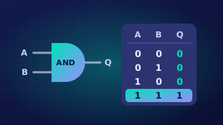
A logic diagram, also called a logic circuit, is a drawing of a Boolean expression. Each gate is drawn as its symbol, and the lines joining the gates are wires that carry a 1 or a 0. Inputs arrive on the left and the final output leaves on the right, so the signal flows across the page in one direction only.
Labels and gate inputs
Give every input its own letter on the left, and label the final output with its own letter on the right. The letters are not numbers to be added or multiplied: they are the names of conditions, reused in the matching Boolean expression and truth table, so a mislabelled circuit describes the wrong problem.
In your diagrams, every AND gate and every OR gate is given exactly two inputs, and every NOT gate exactly one, because those are the rules the gates work by: an AND or OR output is decided by two values, while a NOT gate flips a single value.
Working outwards from the brackets
To draw a circuit from an expression, start at the innermost brackets and work outwards. Draw the gate for the bracketed part first; its output then becomes one of the inputs to the next gate along, joined by a wire. Working in this order keeps the wiring tidy and guarantees you reach the right final output.
A NOT applied to a single input is drawn immediately after that input, before the result feeds into the next gate. So in X OR NOT Y, the NOT gate sits beside Y and its output is what enters the OR gate.
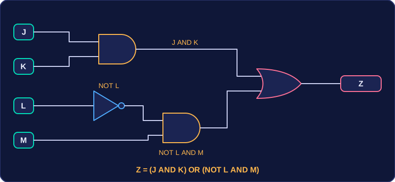
For example, to draw Z = (J AND K) OR (NOT L AND M), begin with the brackets. Draw an AND gate fed by J and K. Next draw a NOT gate on L alone, then feed its output and M into a second AND gate. Then draw an OR gate and feed it the outputs of the two AND gates. Label the result Z: four inputs on the left, four gates and one output on the right.
Practise this
OCR GCSE Computer Science · Boolean Logic