Boolean Logic
Boolean Logic
Contents
Boolean logic works with statements that can only be true or false. These values are written as True and False, or in circuits as 1 and 0. There is no third option, such as 0.5 or 'maybe'. A school locker is either locked or unlocked.
Computers use Boolean logic because their circuits have exactly two states: on and off. A switch inside a chip either lets current through, which we label 1, or blocks it, which we label 0. Every input and output in a logic circuit is therefore a single binary value.
A logic gate is an electronic component in a digital circuit. It receives one or two binary input values, applies a fixed rule, and returns a single binary output value. The rule is fixed: the same input values always give the same output. Inputs are labelled with letters such as A and B, and the output with a letter such as P.
The three gates you need
| Gate | Inputs | Shape of the symbol |
|---|---|---|
| AND | 2 | Straight vertical back edge and a semicircular curved front. Two input lines enter the flat back; one output line leaves the curved front. |
| OR | 2 | The rear edge curves inwards, and the two long sides bow outwards to a sharp point on the output side. Two input lines enter the curved rear; one output line leaves the point. |
| NOT | 1 | A triangle aimed towards the output, with a tiny circle on the pointed end. The input line joins the flat rear edge; the output line comes from the circle. |
Use the shape to tell them apart: AND has a flat back and rounded front, OR a curved back and pointed front, and NOT a triangle with a circle at its point. Only these three gates are needed; NAND, NOR and XOR are not in the specification.
Other accepted notation
You may write T and F instead of 1 and 0, or use gate symbols, or the letter V for OR, instead of a gate's name. Keep to one style throughout a table or answer.
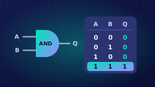
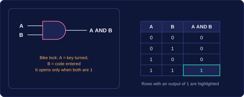
An AND gate is a logic gate that combines its inputs into a single output. With the usual two inputs, its rule is strict: the output is 1 only when both inputs are 1, and a single 0 at either input forces the output to 0.
Think of a bike lock that needs a key turned and a code entered before it releases. Turning the key alone is not enough, and typing the code alone is not enough — both things must happen together. Set key turned = 1 and code entered = 1: only then does the lock give an output of 1 and open.
Truth table for an AND gate
Two inputs give four possible combinations, so the truth table has four rows. Just one of those rows produces an output of 1 — the last one, where A and B are both 1:
| A | B | A AND B |
|---|---|---|
| 0 | 0 | 0 |
| 0 | 1 | 0 |
| 1 | 0 | 0 |
| 1 | 1 | 1 |
Writing AND in an expression
AND is written as A AND B. The result is true only when every condition joined by AND is true, so the answer is 0 the moment any single condition is false. If you joined three conditions as A AND B AND C, the output would be 1 only in the one case where all three are 1.
An AND gate is stricter than an OR gate: a single 1 at one input is never enough to satisfy it, however the other input is set.
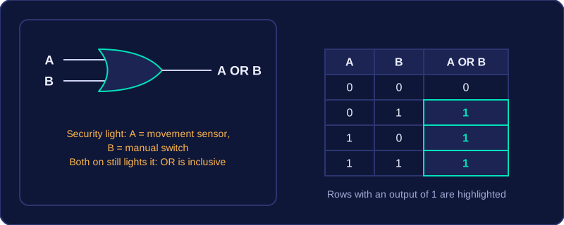
OR is a logic gate with two inputs and one output. It gives an output of 1 when either input is 1, or when both inputs are 1. The only time an OR gate outputs 0 is when both of its inputs are 0.
Truth table for an OR gate
| A | B | A OR B |
|---|---|---|
| 0 | 0 | 0 |
| 0 | 1 | 1 |
| 1 | 0 | 1 |
| 1 | 1 | 1 |
Read each row across: only the top row has two 0 inputs, so it is the only row with an output of 0. The other three rows each contain at least one 1, so each output is 1.
Inclusive OR
An OR gate uses inclusive OR. In everyday speech, "or" can mean one thing or the other but not both. In Boolean logic, A OR B is true when at least one of A and B is true, and it is still true when both are true.
For example, a security light comes on if its movement sensor (M) detects someone OR its manual switch (S) is on. If both happen at once, the light still comes on, so M OR S is true.
OR is written as A OR B, where A and B are the two inputs.
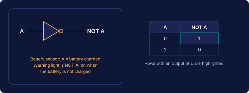
The NOT gate is the simplest logic gate: it has exactly one input and one output, and its output is always the opposite of the value on that input. Send it a 1 and you get a 0; send it a 0 and you get a 1. Because it flips the value like this, the NOT gate is also called an inverter.
Truth table
With one input there are only two possible input values, so the truth table has just two rows:
| A | NOT A |
|---|---|
| 0 | 1 |
| 1 | 0 |
AND and OR each take two inputs, so their truth tables need four rows. A two-row table only ever describes a single input, which is the giveaway that the gate is NOT.
Writing NOT
The output is written as NOT A. Whatever value A has, NOT A holds the other one: if A is 1 then NOT A is 0, and if A is 0 then NOT A is 1.
It works on a whole condition too. A school website shows a banner when it is not a school day, so calling "it is a school day" S, the banner's output is NOT S: on a school day S is 1 and the banner stays off, and at the weekend S is 0 so the banner is 1. Applying NOT twice cancels out, so NOT NOT S behaves exactly like S.
For example, a bike's battery sensor gives 1 while the battery is charged. The warning light must come on when the battery is not charged, so its output is NOT B: when B is 1 the light is 0, and when B is 0 the light is 1 and warns you to recharge.
A truth table records all the input combinations a logic circuit can receive and the output it gives for each one. It lets you see the full behaviour of the circuit without building it.
The number of rows below the heading row is 2 raised to the power of the number of inputs: one input needs 2 rows, two inputs need 4 rows and three inputs need 8 rows. Each extra input doubles the count, because that input can be either 1 or 0, so every row you already had becomes two rows.
Counting in binary
A reliable way to fill the input columns is to treat them as binary numbers and count upwards. With two inputs the patterns run 00, 01, 10 then 11. With three inputs start at 000 and keep counting until you reach 111. This makes it easy to see that no combination is missed and none is repeated. The rows can be in any order and still be correct, as long as every combination appears once.
More than one gate
When a circuit has more than one gate, add a helper column for each gate that sits between the inputs and the final gate. Work out those columns first, then use them to find the final output. For example, for X = (A OR B) AND (B OR C), the helper columns are A OR B and B OR C:
| A | B | C | A OR B | B OR C | X |
|---|---|---|---|---|---|
| 0 | 0 | 0 | 0 | 0 | 0 |
| 0 | 0 | 1 | 0 | 1 | 0 |
| 0 | 1 | 0 | 1 | 1 | 1 |
| 0 | 1 | 1 | 1 | 1 | 1 |
| 1 | 0 | 0 | 1 | 0 | 0 |
| 1 | 0 | 1 | 1 | 1 | 1 |
| 1 | 1 | 0 | 1 | 1 | 1 |
| 1 | 1 | 1 | 1 | 1 | 1 |
The final column is found by applying AND to the two helper values in each row, so you never have to hold several steps in your head at once.
A logic diagram, also called a logic circuit, is a drawing of a Boolean expression. Each gate is drawn as its symbol, and the lines joining the gates are wires that carry a 1 or a 0. Inputs arrive on the left and the final output leaves on the right, so the signal flows across the page in one direction only.
Labels and gate inputs
Give every input its own letter on the left, and label the final output with its own letter on the right. The letters are not numbers to be added or multiplied: they are the names of conditions, reused in the matching Boolean expression and truth table, so a mislabelled circuit describes the wrong problem.
In your diagrams, every AND gate and every OR gate is given exactly two inputs, and every NOT gate exactly one, because those are the rules the gates work by: an AND or OR output is decided by two values, while a NOT gate flips a single value.
Working outwards from the brackets
To draw a circuit from an expression, start at the innermost brackets and work outwards. Draw the gate for the bracketed part first; its output then becomes one of the inputs to the next gate along, joined by a wire. Working in this order keeps the wiring tidy and guarantees you reach the right final output.
A NOT applied to a single input is drawn immediately after that input, before the result feeds into the next gate. So in X OR NOT Y, the NOT gate sits beside Y and its output is what enters the OR gate.
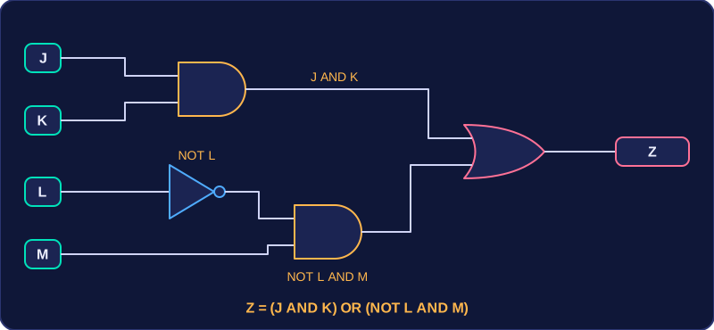
For example, to draw Z = (J AND K) OR (NOT L AND M), begin with the brackets. Draw an AND gate fed by J and K. Next draw a NOT gate on L alone, then feed its output and M into a second AND gate. Then draw an OR gate and feed it the outputs of the two AND gates. Label the result Z: four inputs on the left, four gates and one output on the right.
A Boolean expression is a way of writing how the AND, OR and NOT operators combine inputs to produce a single output. You work out anything in brackets first, just like in maths. For example, in (X OR Y) AND NOT Z, find X OR Y and NOT Z before doing the final AND.
If X = 1, Y = 0 and Z = 0, then X OR Y is 1. NOT Z turns 0 into 1. The last step is 1 AND 1, which gives 1. Without the brackets you could not tell whether the NOT applied to Z alone or to the whole expression, so the brackets show exactly which parts are worked out together.
When NOT is applied to a whole bracketed group, finish the group first and then invert the result. In NOT (P AND Q) with P = 0 and Q = 1, the bracket gives 0, so the final answer is 1.
From a logic diagram to an expression
Start at the inputs and move towards the output. Write what each gate produces, and put brackets around each group so the order is clear. Imagine input M goes through a NOT gate, while N and R go into an OR gate. Those two results then enter an AND gate. The expression is (NOT M) AND (N OR R): NOT M is one group and N OR R is the other. The AND is applied last because it is closest to the output.
You do not need to simplify an expression like this one. The aim is to write or use the expression accurately, with brackets showing the order of operations.
To turn a written scenario into Boolean logic, first find every separate condition that can be true or false. Give each condition a letter, where 1 means the condition is true and 0 means it is false. Next, identify any of the connectives and, or and not; they show how the conditions are combined.
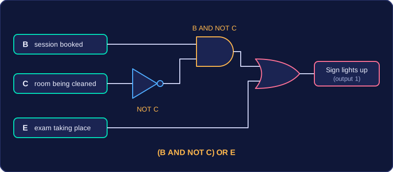
For example, a library's silent-study sign lights up when a study session is booked and the room is not being cleaned, or when an exam is taking place. Let B mean the session is booked, C mean the room is being cleaned, and E mean an exam is taking place. "Not being cleaned" becomes NOT C. The booking and the inverted cleaning condition are joined by AND, while the exam is an alternative, so it is joined by OR. The expression is (B AND NOT C) OR E.
- AND joins conditions that must all be true.
- OR joins alternatives: at least one of them must be true.
- NOT reverses a condition, so "the door is not locked" becomes NOT L.
Use brackets to show which conditions are grouped together, and remember that a letter is just a label for a condition, not a number to calculate with. If both a booking and an exam are happening, OR still makes the overall result true: OR includes the case where both alternatives are true.
Once it is written, the whole expression acts like one condition of its own: it gives 1 when the sign should light up and 0 when it should not.
The same three operators can appear in program conditions such as if statements, but those are covered in a separate subtopic.