Boolean Logic
Boolean logic and gates
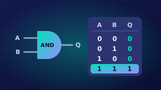
Boolean logic works with statements that can only be true or false. These values are written as True and False, or in circuits as 1 and 0. There is no third option, such as 0.5 or 'maybe'. A school locker is either locked or unlocked.
Computers use Boolean logic because their circuits have exactly two states: on and off. A switch inside a chip either lets current through, which we label 1, or blocks it, which we label 0. Every input and output in a logic circuit is therefore a single binary value.
A logic gate is an electronic component in a digital circuit. It receives one or two binary input values, applies a fixed rule, and returns a single binary output value. The rule is fixed: the same input values always give the same output. Inputs are labelled with letters such as A and B, and the output with a letter such as P.
The three gates you need
| Gate | Inputs | Shape of the symbol |
|---|---|---|
| AND | 2 | Straight vertical back edge and a semicircular curved front. Two input lines enter the flat back; one output line leaves the curved front. |
| OR | 2 | The rear edge curves inwards, and the two long sides bow outwards to a sharp point on the output side. Two input lines enter the curved rear; one output line leaves the point. |
| NOT | 1 | A triangle aimed towards the output, with a tiny circle on the pointed end. The input line joins the flat rear edge; the output line comes from the circle. |
Use the shape to tell them apart: AND has a flat back and rounded front, OR a curved back and pointed front, and NOT a triangle with a circle at its point. Only these three gates are needed; NAND, NOR and XOR are not in the specification.
Other accepted notation
You may write T and F instead of 1 and 0, or use gate symbols, or the letter V for OR, instead of a gate's name. Keep to one style throughout a table or answer.
Practise this
OCR GCSE Computer Science · Boolean Logic