System Modelling
Flowchart symbols

Flowcharts use standard symbols so that anyone reading one can tell what each step does before they read the words written inside it. Four shapes cover almost everything you need.
| Shape | Name | What it shows | Example of the words inside |
|---|---|---|---|
| Oval | Terminator | Where the process starts or ends | Start / End |
| Parallelogram | Input/output | Data entering or leaving the system | Input the swimmer's age / Output the price |
| Rectangle | Process | An action or check the system carries out on the data | Work out the change owed |
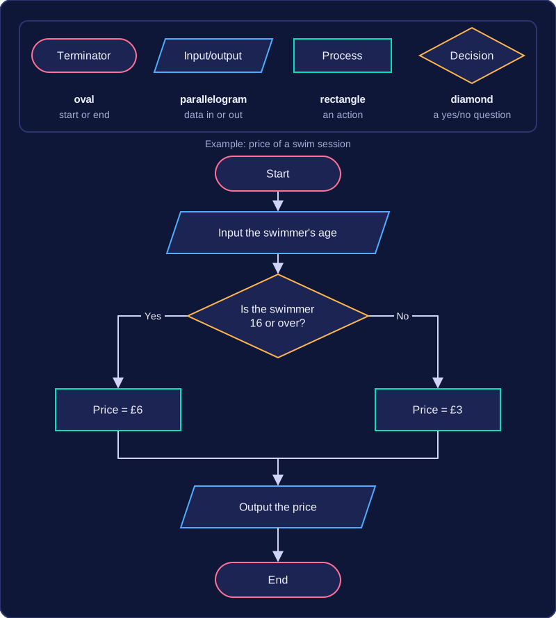
| Diamond | Decision | A question with a yes or no answer, based on a condition | Is the swimmer 16 or over? |
Input and output share one shape, because the same symbol simply means data crossing the edge of the system — in one direction or the other. Some mark schemes call that symbol a rhombus, so don't be confused if you meet the other name.
Decisions split the flow
A decision is the only symbol with two ways out. The condition inside it is written as a question, and the two exits are labelled Yes and No. Yes means the condition is true; No means it is false. The answer a particular piece of data gives decides which path the flow follows next, so leaving an exit unlabelled makes the flowchart impossible to follow.
A short example
A leisure centre charges for a swim session by age. The flowchart opens with a Start terminator, then an input of the swimmer's age, then a decision asking whether the swimmer is 16 or over. The Yes exit leads to a rectangle that sets the price at £6; the No exit leads to a rectangle that sets it at £3. Both rectangles then feed into a single output that shows the price, and one End terminator finishes the flow. Notice that the age is data coming in, the pricing is an action, and only the diamond asks a question.
Practise this
Pearson BTEC Digital Information Technology · Flowcharts